Ls Swap Cooling System Diagram
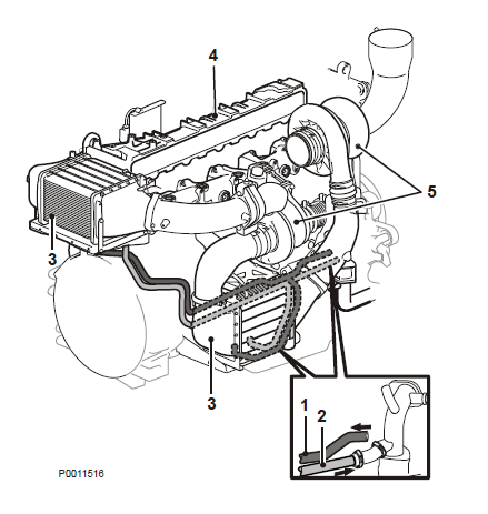
Ls swap cooling system diagram. The MAF sensor must be oriented correctly in the induction Be sure to weld the mounting boss correctly the sensor will only mount one way in the boss see diagram. You will also need the intercooler seal that sits on the top of the supercharger and seals the intercooler brick to the supercharger. Download Ebook Ls3 Engine Cooling System Diagram in many of the F-Body cars so you need a.
It is the highest-rated CFM fan available from manufacturer. LS Crank Pulley Harmonic Balancer Swap Guide. The Complete Swap Manual on page 147.
Engine Cooling System Diagram LS SWAPS. At the moment these trucks are relatively cheap to pick up and can be found with full power AC tilt etc. It requires a high-amp alternator and Be Cools 40.
These swap kits have been engineered by Holley for a easy. GM has released a wide range of Gen III and IV LS engines that deliver spectacular efficiency and performance. One of the most important steps of your swap is to identify the spacing needed.
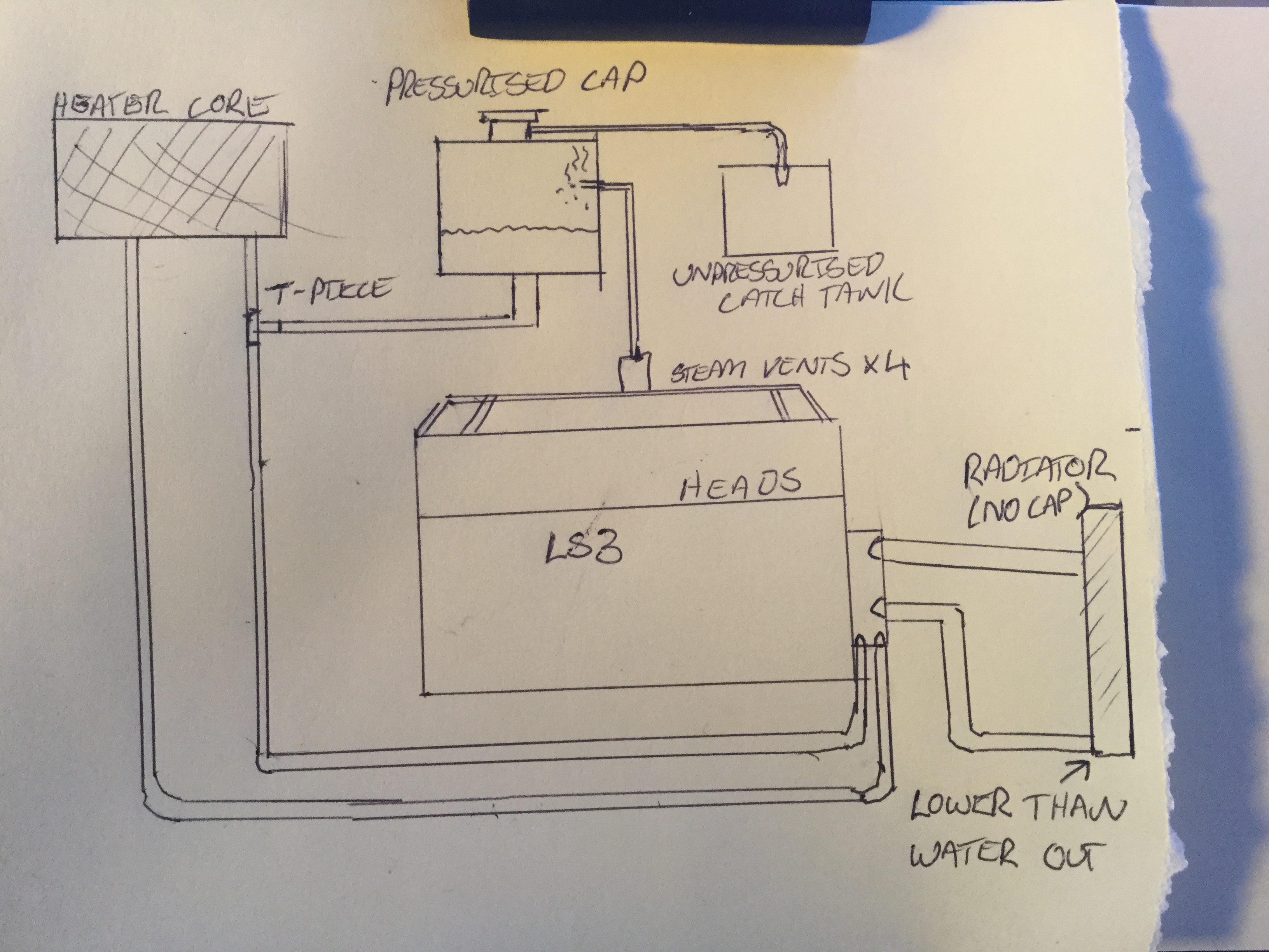
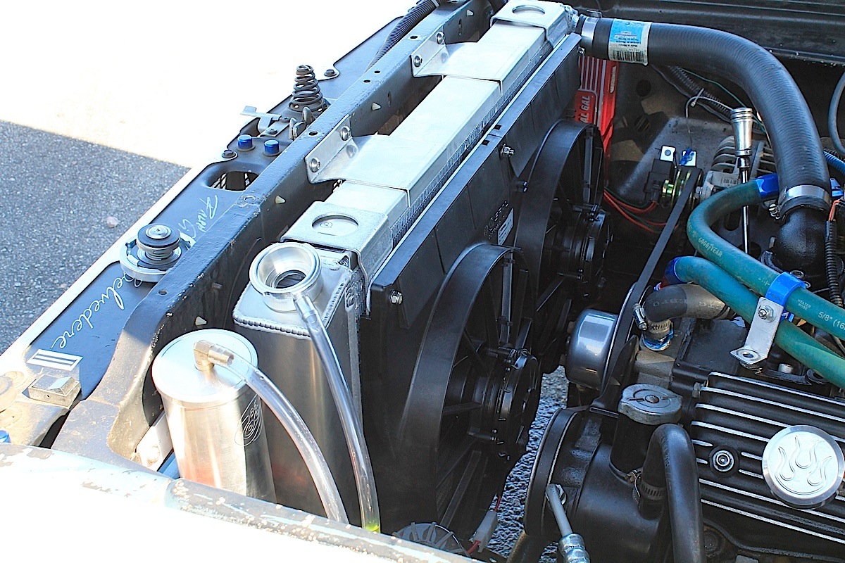
Mar 25 2013 Its no secret that LS engines have been swapped into RX-7s for years. Ls standalone fuse block diagram. Bought a jeep liberty expansion tank for my cooling system to function due to radiator not having a fill cap.
Its very difficult to beat the price per horsepower that they provide. This info is also located in a book called GM LS-Series Engines. The seal is GM part Number 12612467.
Patricia Evans on Ls-swap-cooling-system _BEST_. For the base of.
March 10 2015 by LS Engine DiY.
10 connection must be within the engines air cleaner system and must be inches from the throttle body. Bought a jeep liberty expansion tank for my cooling system to function due to radiator not having a fill cap. For the base of. This info is also located in a book called GM LS-Series Engines. The MAF sensor must be oriented correctly in the induction Be sure to weld the mounting boss correctly the sensor will only mount one way in the boss see diagram. The seal is GM part Number 12612467. LS Swap Guide by LSX Innovations INTRODUCTION. Thats why GM calls it the water pump inlet. The LSA supercharger has become a very popular power adder in the LS market.
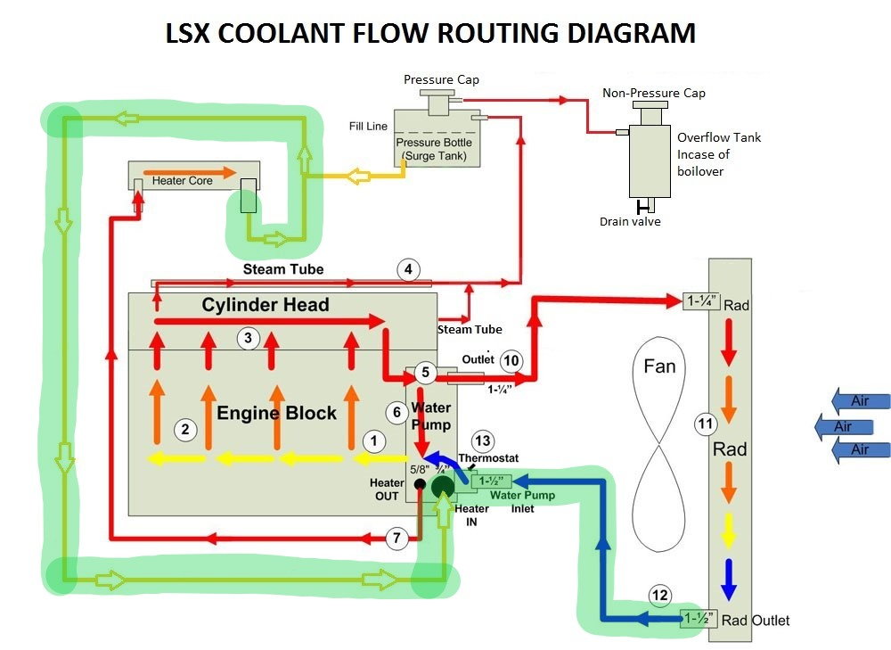
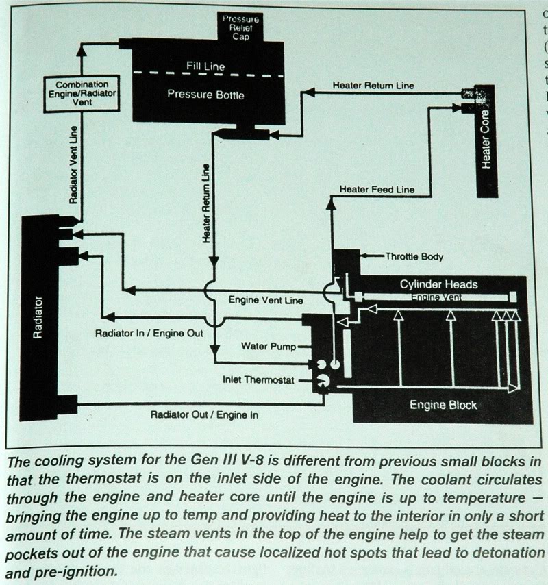
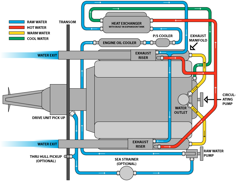
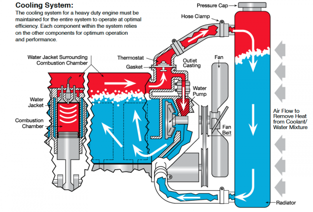
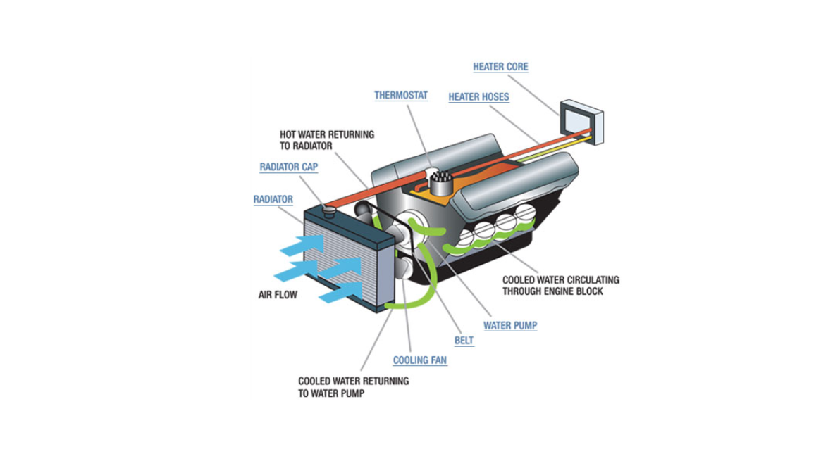
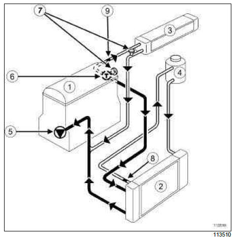
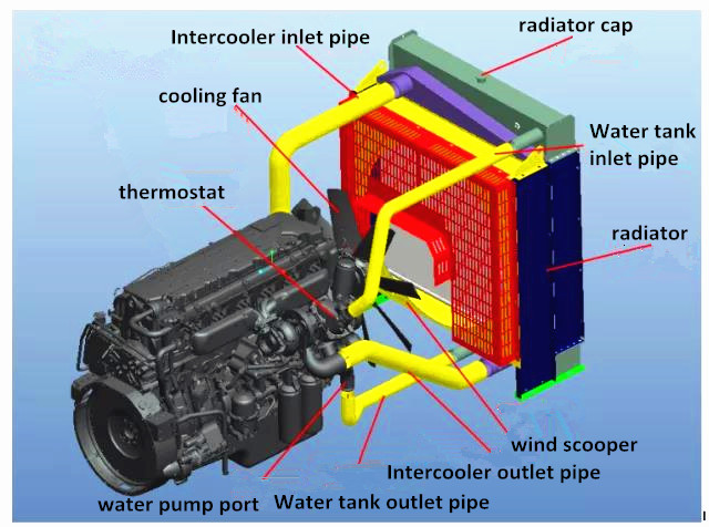
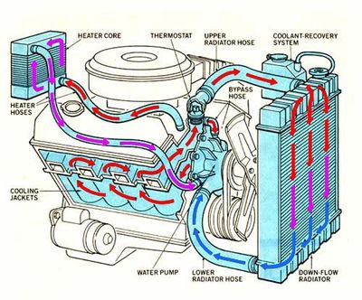
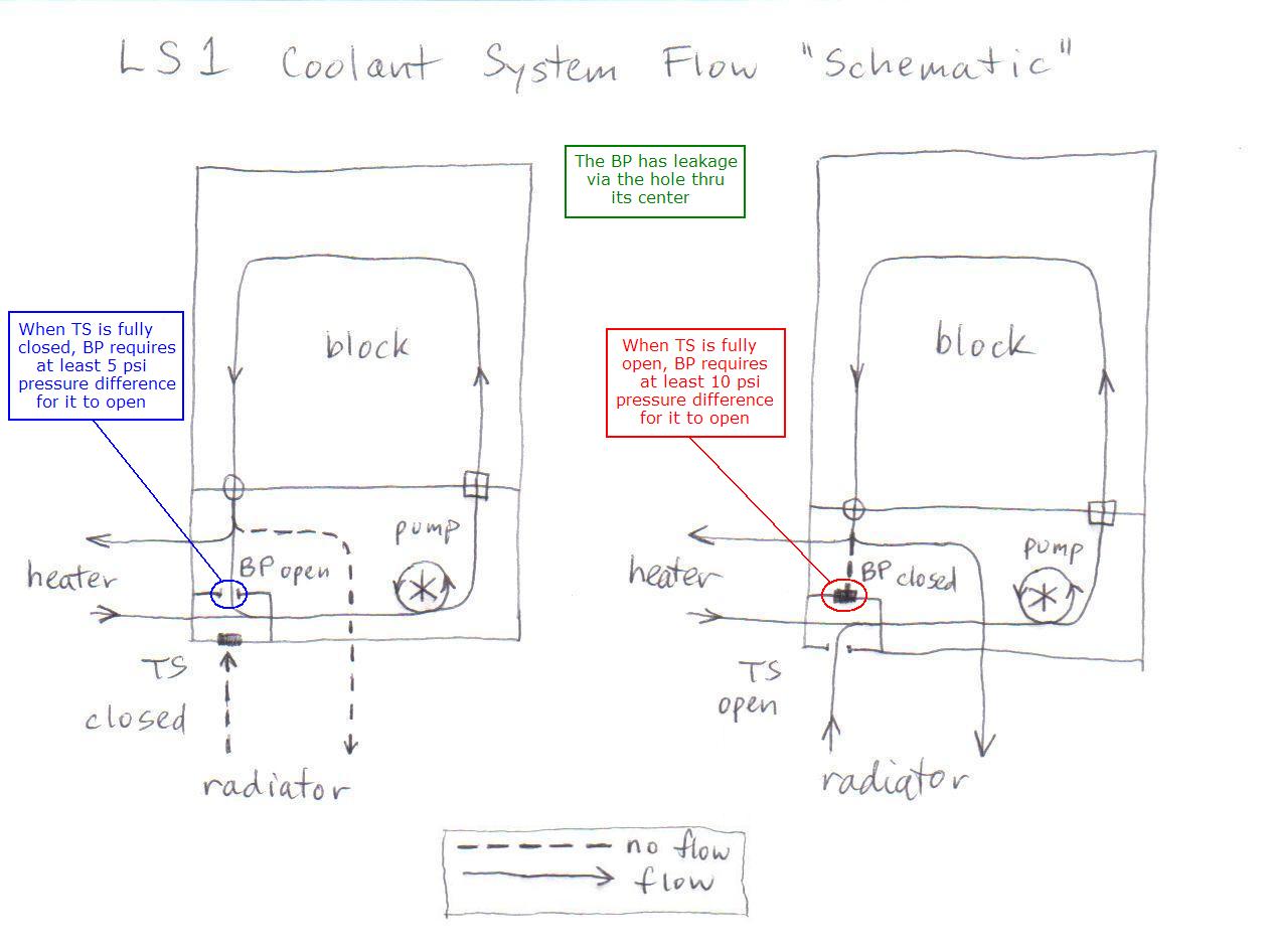
Here is an illustration of how the stock system works. You are going to need 4 relays up to 7 if you want an electric fans 2 fuse blocks some 12 gauge wire and a lot of butt connetors. This LSA Swap guide is intended to walk you through all the basic necessities to get your LSA swap going. 10 connection must be within the engines air cleaner system and must be inches from the throttle body. LS Swap Guide by LSX Innovations INTRODUCTION. Ls3 Engine Cooling System Diagram OMC Closed Cooling System - 2530L 120140 Engine 4Cyl Chevy 1974-UP Half-System OMC Closed Cooling System - 302351 Engine V-8 5058L Ford Cobra Half-System OMC Closed Cooling System - 302351 Engine V-8 Ford 170 to 240 all years with this HP Half-System OMC Closed. On an LS1 the thermostat is located on the water pump inlet.















Post a Comment for "Ls Swap Cooling System Diagram"